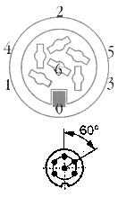
Pasti bermanfaat, .......
http://www.mftech.de/buchsen_en.htm
dan
Aplikasinya, Oscilloscope 2.51 zip file
RC TX PPM Output - Pin Assignment, tuk simulator
Moderator: DeVIN
- DeVIN
- Senior Airman

- Posts: 162
- Joined: 22 May 2007, 05:55
- Location: Tasbi MEDAN
- Contact:
- atari7up
- First Lieutenant

- Posts: 1386
- Joined: 06 May 2008, 10:10
- Location: Medan - (D.A.C)
- Contact:
Re: RC TX PPM Output - Pin Assignment, tuk simulator
Wah..komplit..plit..plit....semuanya ada disana.. 


- dion
- Senior Airman

- Posts: 188
- Joined: 10 Oct 2007, 20:30
- Location: Jogja
- Contact:
Re: RC TX PPM Output - Pin Assignment, tuk simulator
mantap om sharing nya  thanks
- DeVIN
- Senior Airman

- Posts: 162
- Joined: 22 May 2007, 05:55
- Location: Tasbi MEDAN
- Contact:
Re: RC TX PPM Output - Pin Assignment, tuk simulator
Lanjut om, ....
di situ dijelaskan pula bahwa kalo pake tx walkera atau seperti DF4 yang signal ppmnya gak murni, ternyata bisa diambil langsung dari colokan kristal-nya, dsb.
Berarti cukup uptodate tuh infonya.
Salam.
di situ dijelaskan pula bahwa kalo pake tx walkera atau seperti DF4 yang signal ppmnya gak murni, ternyata bisa diambil langsung dari colokan kristal-nya, dsb.
Berarti cukup uptodate tuh infonya.
Salam.
- iwan21
- Administrator

- Posts: 9640
- Joined: 17 Jan 2007, 14:11
- Location: Bekasi
- Contact:
Re: RC TX PPM Output - Pin Assignment, tuk simulator
DeVIN wrote:Lanjut om, ....
di situ dijelaskan pula bahwa kalo pake tx walkera atau seperti DF4 yang signal ppmnya gak murni, ternyata bisa diambil langsung dari colokan kristal-nya, dsb.
Berarti cukup uptodate tuh infonya.
Salam.
yg saya bold itu, persis sama dg kalo kita pake tx asli bawaan WD, dulu utk FMS saya pake remote ini sebabnya dan output PPM ambil dari soket xtal
- BERTHIE FLYER
- Staff Sergeant

- Posts: 237
- Joined: 22 Feb 2008, 22:37
- Location: dulu Medan sekarang Depok
Re: RC TX PPM Output - Pin Assignment, tuk simulator
DeVIN wrote:Pasti bermanfaat, .......
http://www.mftech.de/buchsen_en.htm
dan
Aplikasinya, Oscilloscope 2.51 zip file
ngeri.... sepertinya Pembahasan tingkat tinggi ini.....
- didin
- Major

- Posts: 1792
- Joined: 27 Aug 2008, 11:01
- Location: Pekanbaru
Re: RC TX PPM Output - Pin Assignment, tuk simulator
DeVIN wrote:Pasti bermanfaat, .......
http://www.mftech.de/buchsen_en.htm
dan
Aplikasinya, Oscilloscope 2.51 zip file
Bermanfaat ...? Ya....
Tapi elmu belum nyampai....

- DeVIN
- Senior Airman

- Posts: 162
- Joined: 22 May 2007, 05:55
- Location: Tasbi MEDAN
- Contact:
Re: RC TX PPM Output - Pin Assignment, tuk simulator
@All,
Ya om,...paling tidak disticky nih threadnya tuk informasi dikemudian hari.
Salam.
Ya om,...paling tidak disticky nih threadnya tuk informasi dikemudian hari.
Salam.
- coyo
- Chief Master Sergeant

- Posts: 808
- Joined: 17 Jan 2007, 17:00
- Location: Kota Jababeka, Cikarang
- Contact:
Re: RC TX PPM Output - Pin Assignment, tuk simulator
Kaya'nya penomoran pin di gambarnya salah:

seharusnya begini:

btw, ini PC osciloscope yg lebih advance:
www.zeitnitz.de/Christian/Scope/Scope_en.html
Free for personal use.....

seharusnya begini:

btw, ini PC osciloscope yg lebih advance:
www.zeitnitz.de/Christian/Scope/Scope_en.html
Free for personal use.....
- DeVIN
- Senior Airman

- Posts: 162
- Joined: 22 May 2007, 05:55
- Location: Tasbi MEDAN
- Contact:
Re: RC TX PPM Output - Pin Assignment, tuk simulator
Makasih ya om atas updatenya.
Tapi kayanya keterangannya sama dengan sistem penomorannya, jadi hanya beda sistem penomorannya tetapi arti sama.
dan info tersebut adalah penomoran standar, see http://en.wikipedia.org/wiki/DIN_connector
"Pins on male connectors are numbered (from right to left, viewed from outside of the connector, with the 5 pins upwards, and facing them): 1–4–2–5–3. Holes on female connectors are also numbered 1-4-2-5-3, but from left to right (facing the holes). "

GND: 0 = shielding
Signal: 4
short-circuit 3 with 5
( 1: Bat+, 2: Signal in, 5: Bat+, 6 : +5V )
Salam.
Tapi kayanya keterangannya sama dengan sistem penomorannya, jadi hanya beda sistem penomorannya tetapi arti sama.
dan info tersebut adalah penomoran standar, see http://en.wikipedia.org/wiki/DIN_connector
"Pins on male connectors are numbered (from right to left, viewed from outside of the connector, with the 5 pins upwards, and facing them): 1–4–2–5–3. Holes on female connectors are also numbered 1-4-2-5-3, but from left to right (facing the holes). "

GND: 0 = shielding
Signal: 4
short-circuit 3 with 5
( 1: Bat+, 2: Signal in, 5: Bat+, 6 : +5V )
Salam.